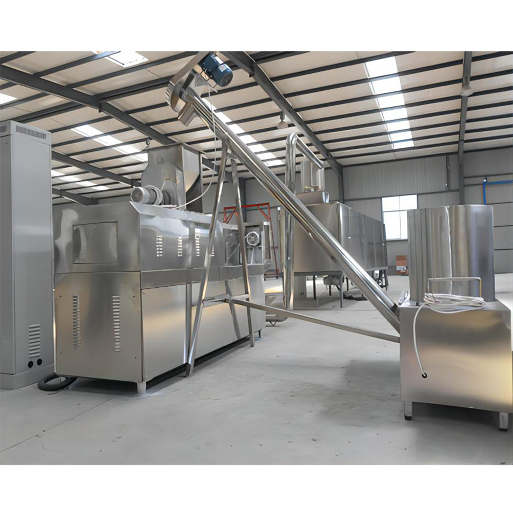
Milk Pasteurizer Temperature Fluctuation: Complete Field Diagnostic and Fix Guide
Pasteurizer temperature unstable is the single most common high-risk fault on the PST-001 continuous HTST (High Temperature Short Time) line used across Esper Foodtech dairy installations. When the holding tube cannot maintain the required 72°C for 15 seconds — or your regenerator is swinging between 68°C and 78°C inside a 60-second window — the divert valve forces product back to the balance tank, you lose run time, and you risk a legal HACCP deviation. This guide walks through every root cause I have diagnosed in the field over 14 years commissioning plate heat exchanger (PHE) pasteurizers, with the exact numbers, part names, and step-by-step fixes that will get you back to holding ±0.5°C.
- Symptom: Holding tube temperature swings more than ±0.5°C over a 60-second window
- Symptom: F-DD (forward-divert) valve cycling to divert more than once per 30 minutes of steady run
- Symptom: Steam modulating valve hunting — visible stem oscillation exceeding 2 mm every 5 seconds
- Symptom: Hot water setpoint reaches setpoint but product outlet overshoots by 1.5°C to 4°C
- Symptom: PID output on the steam valve pinned at 95–100% with no corresponding temperature rise
- Symptom: Product flow rate varies more than 100 L/h on the magnetic flow meter during a run
- Symptom: Plate pressure drop on the regenerator side has increased 0.3 bar above baseline within 8 hours
- Symptom: Divert valve trips within 10 minutes after a CIP cycle despite a clean probe
- Symptom: PID auto-tune fails or returns an error code on the Yokogawa UT55A or Allen-Bradley 5/05 controller
What Causes — Steam Modulating Valve Sizing and Seat Wear (Spirax Saray KE or Samson 3213)?
The number one cause of unstable pasteurizer temperature is an oversized or worn steam control valve. On PST-001 lines, the steam valve is typically a Spirax Saray KE71 pneumatic positioner valve or a Samson 3213-0750 with a type 3271 electropneumatic positioner. When the seat begins to erode — usually after 18 to 24 months of service on saturated steam at 6 bar — the valve loses its true modulating range and begins to operate in essentially a two-position (bang-bang) mode. The controller output may show 35%, but the actual flow is either near zero or fully open.
Diagnosis steps:
- Step 1: With the line running at full product flow (typically 5,000 L/h on a PST-001-5000), record the PID output on the controller. A healthy steam valve runs at 28–42% open during steady-state pasteurization at 72°C.
- Step 2: Command a 2°C setpoint step change (72°C to 74°C) and watch the stem. If the stem moves smoothly and the temperature settles within 45 seconds with no more than one overshoot cycle, the valve is healthy. If the stem slams to 100% then drops to 5%, the seat is leaking.
- Step 3: Perform a stroke test. Command 0%, 25%, 50%, 75%, 100%. At each step, measure the actual stem position with a caliper against the positioner feedback scale. Linear error must be under 3%. Anything over 8% means the plug and seat need replacement.
- Step 4: Check the air supply to the positioner. Spirax Saray KE71 requires 1.4 bar instrument air at 20 L/min. A clogged air filter regulator (usually a SMC AW20) will cause positioner hunting that looks identical to valve wear.
Fix: Replace the plug and seat kit (Spirax Saray part KE71-PTFE-KIT, approximately USD 380) and the PTFE valve seat. Re-tune the positioner with a 25-50-25 calibration sequence. If the valve body is sound and only the seat is worn, full rebuild takes about 90 minutes. After rebuild, the PID output should sit at 30–35% at steady state.
What Causes — Plate Heat Exchanger Fouling (APV H17 / GEA NT100 Plate Pack)?
The second most common cause is protein and mineral fouling on the heat transfer plates. The PST-001 uses either an APV H17-BC plate pack or a GEA NT100 with 60 to 90 plates depending on the duty. Milk protein denatures at 65°C and forms a film; calcium phosphate scale forms above 70°C and grows rapidly. Even a 0.2 mm fouling layer on the hot side plates can drop the overall heat transfer coefficient (U-value) from a baseline 3,500 W/m²·K down to 1,800 W/m²·K — meaning your steam valve opens further to compensate, runs near saturation, and begins to hunt.
Diagnosis steps:
- Step 1: Compare the current hot water to product approach temperature to commissioning baseline. A clean PST-001 should show a maximum approach temperature of 2.5°C. If the approach is now 5°C or more, fouling is severe.
- Step 2: Measure pressure drop across the heat section. Baseline on a APV H17 at 5,000 L/h is 0.8 bar. If you read 1.4 bar or higher, the plates are blocked with protein and mineral scale.
- Step 3: Inspect the CIP thermometer data. If caustic (NaOH 1.5%) return temperature from the PHE is more than 4°C colder than supply temperature, the CIP is not contacting the fouled surface — usually because the foulant has formed a shiny protein skin that needs enzymatic cleaner (Novozymes P3-cosme 0.5%) to break.
- Step 4: Open the inspection port after CIP and pull a single plate from the heat section (typically plate 18 or 22). Visual: a clean plate has a mirror finish with visible herringbone pattern. Fouled plates show a cloudy amber film (protein) or a hard white crust (calcium phosphate).
Fix: For mild protein foulant, run an extended enzymatic CIP with circulation for 60 minutes at 65°C. For mineral scale, use a 1.5% phosphoric or nitric acid wash (P3-oxonia) at 70°C for 45 minutes — never exceed 75°C with nitric on 304 stainless plates. For severe fouling, the plate pack must be disassembled, plates individually scrubbed with a soft bristle brush and 1% NaOH, rinsed, inspected for cracks (dye-penetrant test kit), regasketed with new NBR or EPDM gaskets (APV part H17-G-NBR), and re-torqued to the plate pack specification (typically 4.2 bar clamping pressure on H17, 4.6 bar on GEA NT100).
What Causes — Magnetic Flow Sensor Drift (Endress+Hauser Promag P200)?
Flow sensor drift is the silent killer of temperature stability. The PID controller on a PST-001 uses feed-forward compensation: if the flow meter reports the flow is constant, the PID does not anticipate a load change. But if the flow is actually oscillating by 200 L/h and the meter is too fouled to see it, the steam valve is always reacting late. The standard flow sensor is an Endress+Hauser Promag P200 DN50 with a Promag 400 transmitter.
Diagnosis steps:
- Step 1: At a steady pump speed (check the VFD display on the Grundfos CR5-30 or similar booster pump), the flow rate on the transmitter should be rock steady within ±20 L/h over 5 minutes. If the display flickers by more than ±80 L/h with no pump speed change, the electrodes are dirty.
- Step 2: Check the empty pipe detection alarm. A faulty grounding ring (a common cause of noise) will trigger EPD alarm and the controller will hold the last value.
- Step 3: Verify calibration against a known volume. Pump 1,000 L from a calibrated balance tank through the meter. The totalizer must read between 999.2 and 1,000.8 L. Anything outside that range requires recalibration.
- Step 4: Inspect the electrode ports in the sensor tube. With the line drained and the sensor flange-bolt removed, look at the two 316L electrode faces flush with the inside wall. A healthy electrode is polished. A protein film on the electrode (milky white-yellow) creates a capacitor that filters out the real flow signal.
Fix: Remove the sensor and clean the electrodes with a soft cloth and 0.5% NaOH solution. Do not use abrasives — a scratched electrode face permanently alters the meter calibration. Recalibrate using the 5-point reference procedure in the Promag 400 menu (Menu: Calibration — Flow — K-factor — Reference). If the meter is more than 4 years old and has been on raw milk service, replace the grounding rings (E+H part 50098174) as the PTFE lining erodes and exposes the stainless ring to electrolytic corrosion.
What Causes — PID Controller Tuning Has Wandered (Yokogawa UT55A / Allen-Bradley MicroLogix 1400)?
A pasteurizer PID loop that ran perfectly for 2 years can suddenly go unstable when something changes upstream — a new milk supply with different fat content, a regenerator gasket leak that lowers the heat recovery ratio, or even a steam supply pressure drop from 6 bar to 5.5 bar. The PST-001 ships from the factory with the heat loop PID tuned for a specific set of conditions. When those conditions drift, the original P, I, and D values become wrong.
Diagnosis steps:
- Step 1: On the Yokogawa UT55A controller, navigate to Setup — PID — PID1 and note the current P, I, and D. Factory baseline for PST-001 heat loop is P = 3.5, I = 45 seconds, D = 8 seconds.
- Step 2: Perform a 10% step test on the setpoint (from 72°C to 79°C). The temperature should rise, overshoot by no more than 0.8°C, then settle within 75 seconds with at most one cycle of oscillation. If you see three or more oscillation cycles before settling, the gain is too high. If the temperature rises too slowly and never reaches setpoint, the gain is too low.
- Step 3: Check the derivative filter time constant. If D is set above 12 seconds, the loop will react sharply to noise on the RTD signal and cause hunting.
- Step 4: Verify the controller output is not saturating. With a 72°C setpoint and clean plates, output should be 30–40%. If output is at 95% but temperature is below setpoint, the loop is not the problem — look at steam supply or plate fouling first.
Fix: Run the Yokogawa auto-tune (Setup — Tuning — Auto — Start). The controller will inject a step response and compute new PID values. Auto-tune typically takes 8 to 15 minutes. If auto-tune fails (returns E-1 error), manually adjust: cut P by 30% (try P = 2.5), increase I to 60 seconds, set D to 6 seconds. Manually tune using the Ziegler-Nichols method: increase P until sustained oscillation, record the oscillation period Pu and the gain Ku. Final values: P = 0.6·Ku, I = 0.5·Pu, D = 0.125·Pu. After tuning, the temperature should hold within ±0.5°C of setpoint indefinitely.
What Causes — RTD Sensor Wiring and Thermowell Issues (PT100 Class A 3-Wire)?
The temperature sensor is the eyes of the PID loop. A noisy RTD signal looks identical to a real temperature swing, and the controller will chase the noise. The PST-001 uses Endress+Hauser TR45 PT100 Class A 3-wire RTDs in 6 mm stainless thermowells at the holding tube outlet and the regenerator outlet. A single broken shield wire or corroded thermowell connection can introduce 0.5°C of noise into the control loop.
Diagnosis steps:
- Step 1: With the line running at steady state, watch the temperature readout at 1-second resolution. A real temperature swing is slow and smooth. Electrical noise shows up as sharp spikes (±0.3°C in 1 second, then back).
- Step 2: Check the resistance between the RTD leads at the transmitter (E+H TMT181). Between the two red leads (RTD element), you should read 110.5 ohms at 25°C. Between any lead and the shield, you should read infinite. A finite reading means the shield is shorted and the wire must be replaced.
- Step 3: Pull the RTD from the thermowell and inspect. There should be a thin film of thermal conductive paste (Omegatherm 201) at the tip. If the well is dry, the thermal response time is 4x slower and the PID sees the temperature late.
- Step 4: Verify the thermowell is not air-locked. A small steam bubble in the well insulates the RTD from the milk. Tap the well with a soft mallet — if the readout jumps 0.5°C, you have an air pocket.
Fix: Replace the thermal paste, ream the thermowell with a 6 mm brass brush to remove milkstone, install the RTD with the tip spring-loaded against the well bottom. Replace any RTD with more than 0.3 ohm lead-to-lead resistance imbalance (measure between wires 1-2, 2-3, 1-3 — the difference should be less than 0.3 ohm). Use shielded twisted pair Belden 8453 cable for the entire run from sensor to transmitter, with the shield grounded at one end only (the transmitter end).
What Causes — Steam Supply Pressure Instability (Spirax Saray BRV71 Reducing Station)?
The steam valve can only modulate against a steady upstream pressure. If the plant steam header pressure swings, the valve output swings even when the valve position is constant. The PST-001 expects 6 bar saturated steam at the reducing station inlet and 3.5 bar at the steam valve inlet. The Spirax Saray BRV71 reducing valve with a 1:2 pilot ratio regulates this. A faulty pilot diaphragm will cause the downstream pressure to oscillate between 2.8 bar and 4.2 bar, which translates directly into 3°C swings at the product outlet.
Diagnosis steps:
- Step 1: Install a pressure data logger (or use the existing Wika S-11 transmitter) on the steam line downstream of the reducing valve. Record at 1 Hz for 10 minutes. Pressure should be steady within ±0.1 bar. Anything more means the reducing valve needs service.
- Step 2: Check the pilot sense line — the 6 mm copper tube that connects downstream pressure to the pilot. A kink or blockage here will make the reducing valve sluggish.
- Step 3: Verify the steam trap on the drip leg upstream of the reducing valve. A flooded trap (usually a Spirax Saray FT14 float and thermostatic trap) feeds condensate into the valve and causes steam pressure fluctuations. Confirm trap operation with an ultrasonic tester (UE Systems Ultraprobe 100) — a healthy trap clicks open and closed every 2 to 5 seconds at full load.
- Step 4: Check the boiler header pressure with the same data logger. If the plant header swings more than 0.5 bar, no amount of reducing valve service will fix the line — you need to add a steam accumulator or fix the boiler controls.
Fix: Rebuild the BRV71 reducing valve pilot diaphragm (Spirax kit BRV71-PD, includes main valve seat, pilot diaphragm, and adjustment spring). Set the downstream pressure to exactly 3.5 bar by turning the pilot spring nut clockwise to raise, counterclockwise to lower. Test by closing the steam valve downstream and watching the pressure — it should rise no more than 0.3 bar (the proportional offset) and hold steady. Clean or replace the FT14 trap if needed.
What Causes — Holding Tube Design and Bypass Leakage (Sanitary Three-Way Divert Valve)?
The least obvious cause of temperature instability is a leaking divert valve. The PST-001 holding tube ends in a Alfa Laval Unique DV-3 sanitary three-way divert valve. When this valve is in the forward-flow position, a worn seat can allow a small stream of cold milk from the balance tank to leak back into the holding tube outlet, mixing with the hot pasteurized milk and dropping the apparent temperature by 2°C to 5°C. The PID reacts by adding steam, the temperature overshoots, the divert valve opens further, the leak reduces — and the cycle continues.
Diagnosis steps:
- Step 1: With the line stopped but the balance tank full of cold water at 10°C, install a temperature sensor on the holding tube outlet and close the main product isolation valve. If the temperature at the holding tube outlet begins to drop without any pump running, the divert valve is leaking backward.
- Step 2: Measure the seat lift on the Unique DV-3. With the valve in forward position, the actuator top plug should compress the seat by 2 mm. Use a depth gauge to verify. If the compression is less than 1.5 mm, the seat is worn.
- Step 3: Bench test the valve. Remove from the line and pressurize the forward-flow port to 2 bar with the valve in divert position. Any leakage past the seat to the divert port is unacceptable — drips should be zero.
- Step 4: Inspect the valve position feedback switch (usually a Sucotech IS-200 inductive sensor). A faulty switch can falsely signal valve travel and confuse the interlock PLC.
Fix: Replace the seat and plug seal kit on the DV-3 (Alfa Laval part 9657001015, includes upper seat, lower seat, plug seal, and shaft seal). Install the new seats, torque the actuator to specification (3.8 Nm on the top plug), and verify the position feedback switch with a multimeter. Reinstall and run the line — temperature should stabilize immediately if the leak was the source.
| Symptom | Most Likely Root Cause | Quick Diagnostic | Typical Fix Time |
|---|---|---|---|
| PID output above 90%, temperature below setpoint | Plate fouling (U-value drop) | Check approach temperature > 5°C | 2 hours (enzymatic CIP) to 8 hours (full plate clean) |
| Rapid oscillation ±2°C within 30 seconds | Steam valve hunting / worn seat | Stroke test, 25-50-75-100% command | 90 minutes for seat rebuild |
| Slow drift over 5 to 10 minutes, then recovery | Steam supply pressure instability | Pressure log downstream of BRV71 | 3 hours for pilot rebuild |
| Temperature spikes ±0.3°C in 1 second intervals | RTD electrical noise | Resistance check between leads | 30 minutes to re-paste and re-shield |
| Temperature falls only during flow spikes | Magnetic flow sensor drift | Compare totalizer to known volume | 45 minutes for electrode clean |
| Persistent overshoot after setpoint change | PID gain too high | Step test, count oscillation cycles | 15 minutes for auto-tune |
| Random 2 to 5°C drop with no setpoint change | Divert valve seat leak | Static leak test with cold water | 2 hours for DV-3 rebuild |
Frequently Asked Questions
Q: How tight should my temperature hold be on a properly running PST-001?
A: A well-tuned, clean PST-001 with healthy sensors should hold the holding tube outlet temperature within ±0.3°C of the 72°C setpoint during steady-state operation at design flow (5,000 L/h). Regulatory bodies typically require ±0.5°C. If you are seeing ±1.0°C, you are operating on borrowed time — the line is one small change away from a divert event.
Q: Why does my temperature swing only get worse after CIP?
A: Two common reasons. First, the CIP did not fully remove the protein film and instead loosened flakes that are now circulating in the regenerator, intermittently blocking flow channels. Second, the hot caustic at 80°C thermally cycles the steam valve positioner and loosens a worn seat, making it leak more aggressively. Run an enzymatic follow-up CIP and inspect the steam valve seat.
Q: Can I just lower the setpoint to 71°C to stop the divert valve from tripping when the temperature swings down?
A: Absolutely not. The 72°C for 15 seconds holding requirement is a legal HACCP critical control point. Lowering the setpoint below the regulatory minimum is a food safety violation and will result in product recall, regulatory action, and potential criminal liability. The correct response is to find and fix the root cause of the swing.
Q: How often should I rebuild the steam valve and the divert valve on preventive maintenance?
A: For a single-shift operation (8 to 10 hours per day), rebuild the steam valve seat every 18 months and the divert valve seats every 24 months. For double-shift operations, halve those intervals. Document the rebuild in your maintenance log and trend the PID output before and after — a successful rebuild will drop the steady-state PID output by 8 to 12 percentage points.
Q: My PID auto-tune fails every time. What am I doing wrong?
A: Auto-tune requires a stable process. If the line has fouled plates, a worn steam valve, or noisy RTD signal, the auto-tune algorithm cannot extract a clean response curve and will fail with E-1. Fix the mechanical issues first (clean plates, rebuild valve, replace noisy RTD), then run auto-tune. Auto-tune should be the last step, not the first.
Q: What is the difference between ±0.5°C and ±1.0°C in actual product safety margin?
A: At 72°C with a 15-second hold, you achieve a 5-log reduction of Coxiella burnetii (the target pathogen for milk pasteurization). At 71°C, you achieve roughly a 4-log reduction — one order of magnitude less. At 70°C, you are below the pasteurization threshold and the product is legally unpasteurized. A ±1.0°C swing means you are spending real time at 71°C or below, which is why the regulatory limit is ±0.5°C.
If your PST-001 has been running cleanly for years and suddenly starts swinging, do not assume the controller has failed. In 90% of cases I have diagnosed in the field, the root cause is mechanical: a worn valve seat, fouled plates, or a dirty sensor. Fix the mechanics first, then tune the controller. Email me at [email protected] with your PID output readings, pressure drop data, and a brief description of the symptom — I can usually point you to the root cause within one exchange and arrange on-site service if needed across Esper Foodtech installations.
Learn more: cooking oil processing applications
Get a quote: [email protected]